MPLS Configuration Gns3 Lab
This article is about MPLS (Multi-Protocol Label Switching, which is commonly used by telecom operators (ISP) as connectivity solution of long distance. Before going to technical discussion, a first important observation is that the configuration of this technology in the corporate environment or enterprise is totally different from the setting the MPLS in the cloud service provider (ISP).
Learn about “what is a vpn client”
Why MPLS Is Used
MPLS is lable-base fast switching, which forward the packets on basis of labels. Normally routing devices use the process-switching in which whenever they received a packet, they checks it’s IP address and forward ti after matching with routing table, this process may involved “send ARP request for MAC address”. Imagine, when there is hign traffic like in case of VOIP , this Process become a little slow. For Example a IP Phone call may using 100packets/S then router have to performed the processor for every 100 packets. Unlike other Layer 2 technologies i.e. HDLC, ATM and Frame-Relay that were traditionally used in the long-distance, MPLS s uses a label base Layer technology also called labels base routing. So Solution is the MPLS, where router assign a label to each packet for fast switching.
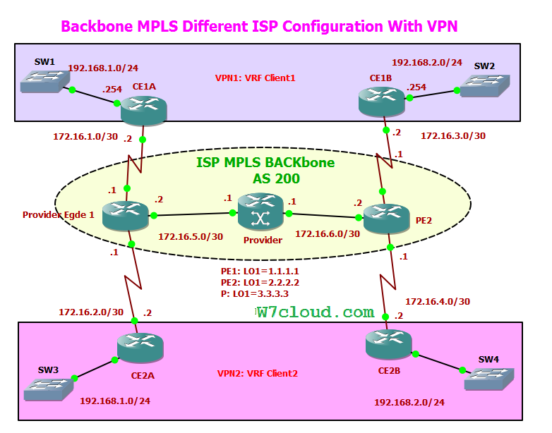
Following is the MPLS cloud diagram for our lab which is created in GNS3. Where you can see that we have a service provider network which is tagged as “ISP MPLS backbone” and there are two customer Edge.

Before going into configuration, there are several fundamental concepts that the reader must keep in mind to understand the role of the elements involved in the scenario
The customer Edge (CE)
The customer Edge (CE) is the equipment installed in remote units of the company that will receive the connectivity solution provided by the provider.
The Provider Edge (PE)
The Provider Edge (PE) is the operator’s router connected to one (or more) client router, PEs are connected with P router. The P (Provider) s will the other routers distributed by cloud MPLS representing the network infrastructure operator.
Virtual Routing and Forwarding
Another key concept is the technology VRF ( Virtual Routing and Forwarding ) that brings two other equally important elements: the RD ( Route Distinguish er ) and RT ( Route Target ) .Through VRF you can create multiple instances of the routing table, to exist in a router and work simultaneously. This increases functionality by allowing network paths to be segmented without using multiple devices. No individual VRFs traffic between subnets of all customers of the operator would compose a single routing table, which it would be bad from a security point of view. Another common benefit is that it makes it possible for customers to use the same address networks.
However, at some point it is necessary that the routes between the router d the company ( C E) and carrier router (PE) are redistribute to a BGP process in PE.
Here comes a problem: It is clear that it is possible to have duplicate addresses across VRFs because they represent different routing tables, This is only possible through the addition of a identifies pain on the routes to make them unique is called RD ( Route Distinguisher ).
MPLS Configuration Gns3 Steps
In the scenario presented in this article we have two VRFs named Client1 and Client 2 to be identified as follows:
– VRF Client 1 , R D 65001: 1 11 RT 6500 1 : 1
– VRF Client 2, RD 65002: 222 , RT 65002 : 2
For easy understanding, I am dividing the configuration process in the following steps:
- IP addresses Configuration
- EIGRP configuration in the Carrier Cloud (AS 200)
- Creation and Association of VRF and RD Configuration / RT
- EIGRP routing configuration on PE and CE
- EIGRP and BGP Route Redistribution Configuration
- MP-BGP configuration in (s) PE
Steps 1 and 2 do not concern with the MPLS configuration itself, but these are the prerequisites for this lab. I have configured this lab in GNS3 with router IOS “c3660-telcoentk9-mz.124-13b.bin”, you can use any other router with MPLS support.
1) Basic Interfaces Configuration and IP Addresses
Following are the IP setting but notice that the interfaces that connect to the CE routers do not have this setting, since the traffic to the PE is pure IP.
PE1 Configurations
PE1 (config) # int loopback 1

PE1 (config-if) # ip address 1.1.1.1 255.255.255.255

PE1 (config-if) # int f0 / 0

PE1 (config-if) # ip address 172.16.5.2 255.255.255.252

PE1 (config-if) # mpls ip

PE1 (config-if) # int s1 / 0

PE1 (config-if) # clock rate 64000

PE1 (config-if ) # ip address 172.16.1.1 255.255.255.252

PE1 (config-if) # no shut

PE1 (config-if) # int s2 / 0

PE1 (config-if) # clock rate 64000

PE1 (config-if) # ip address 172.16 .2.1 255.255.255.252

PE1 (config-if) # no shut
PE2 Configurations
PE 2 (config) # int loopback 1

PE 2 (config-if) # ip address 2.2.2.2 255.255.255.255

PE 2 (config-if) # int f0 / 0

PE 2 (config-if) # ip address 172.16. 6 .2 255.255.255.252

PE 2 (config-if) # mpls ip

PE 2 (config-if) # int s1 / 0

PE 2 (config-if) # clock rate 64000

PE 2 (config-if) # ip address 172.16. 3 .1 255.255.255.252

PE 2 (config-if) # no shut

PE 2 (config-if) # int s2 / 0

PE 2 (config-if) # clock rate 64000

PE 2 (config-if) # ip address 172.16. 4 .1 255.255.255.252

PE 2 (config-if) # no shut
P Configurations
P (config) # int loopback 1

P(config-if) # ip address 3.3.3.3 255.255.255.255

P(config-if) # int f0 / 0

P (config-if) # ip address 172.16. 5. 1 255 255 255 252

P(config-if) # mpls ip

P(config-if) # int f1 / 0

P (config-if) # ip address 172.16. 6 .1 255.255.255.252

P (config - if ) # mpls ip

P(Config-if) # no shut
2) IGP routing (EIGRP) in the Carrier Cloud (AS 200)
This second stage is also very basic, consisting only in the configuration of an IGP routing protocol which either in the cloud service provider.
PE1 (config) # router eigrp 200

PE1 (config-router) # network 172.16.0.0

PE1 (config-router) # network 1.1.1.1

PE1 (config -router) # no auto-summary
PE2 (config) # router eigrp 200

PE2 (config-router) # network 172.16.0.0

PE2 (config-router) # network 2.2.2.2

PE2 (config-router) # no auto-summry
P (config) # router eigrp 200

P (config-router) # network 172.16. 0.0

P (config-router) # network 3.3.3.3

P (config - router) # no auto-summary
3) Creation and Association of VRF and RD configuration / RT
the following configuration is required only at edge routers (PE) , since the routers of the company (EC) did not have knowledge of MPLS. Notice that in each edge router create two VRFs and RD / RT values previously defined. Finally, associated each VRF with its respective interface (client).
PE1 (config) #ip vrf Client1
PE1 (config-vrf ) #rd 65001: 111
PE1 (config-vrf) # route-target BOTH 65001: 1
PE1 (config-vrf) #exit
PE1 (config) #ip vrf Client2
PE1 (config-vrf) #rd 65002: 222
PE1 (config -vrf) # route-target BOTH 65002: 2
PE1 (config-vrf) #exit
PE1 (config) #int s2 / 0
PE1 (config-if) #ip vrf forwarding Client1
PE1 (config-if) #ip address 172.16.1.1 255.255.255.252
PE1 (config-if) #exit
PE1 (config) #int s2 / 1
PE1 (config-if) #ip vrf forwarding Client2
PE1 (config-if) #ip address 172.16.2.1 255.255.255.252
PE1 (config-if) #exit
PE2 (config) #ip vrf Client1
PE2 (config-vrf ) #rd 65001: 111
PE2 (config-vrf) # route-target BOTH 65001: 1
PE2 (config-vrf) #exit
PE2 (config) #ip vrf Client2
PE2 (config-vrf) #rd 65002: 222
PE2 (config -vrf) # route-target BOTH 65002: 2
PE2 (config-vrf) #exit
PE2 (config) #int s2 / 0
PE2 (config-if) #ip vrf forwarding Client1
\PE2 (config-if) #ip address 172.16.3.1 255.255.255.252
PE2 (config-if) #int s2 / 1
PE2 (config-if) #ip vrf forwarding Client2
PE2 (config-if) #ip address 172.16.4.1 255.255.255.252
PE2 (config-if) #exit
Ignore the message “% Serial Interface / 1 IP address 172.16 .x.x removed due to enabling VRF Client2 ” during above configurations.
4) EIGRP routing configuration on PE and CE
The next step is the configuration of a routing protocol between the companies so that the provider can know the routes advertised by the company. This configuration process is quite simple.
CE1A (config) #router eigrp 65001

CE1A (config-router) #network 192.168.1.0

CE1A (config-router) #network 172.16.0.0

CE1A (config-router) #no auto-summary
CE2A (config) #router eigrp 65002

CE2A (config-router) #network 192.168.1.0

CE2A (config-router) #network 172.16.0.0

CE2A (config-router) #no auto-summary
PE1 (config) #router eigrp 1

PE1 (config-router) # address-family ipv4 vrf Client1

PE1 (config-router-af) # autonomous-system 65001

PE1 (config-router-af) #network 172.16.0.0

PE1 (config-router-af) #no auto-summary

PE1 (config-router-af) #

PE1 (config-router-af) # address-family ipv4 vrf Client2

PE1 (config-router-af) # autonomous-system 65002

PE1 (config-router-af) #network 172.16.0.0

PE1 (config-router-af) #no auto-summary
CE1B Configurations
CE1B (config) #router eigrp 65001

CE1B (config-router) #network 192.168. 2 .0

CE1B (config-router) #network 172.16.0.0

CE1B (config-router) #no auto-summary
CE2B (config) #router eigrp 65002

CE2B (config-router) # network 192.168. 2 .0

CE2B (config-router) #network 172.16.0.0

CE2B (config-router) #no auto-summary
PE2 (config) #router eigrp 1

PE2 (config-router) # address-family ipv4 vrf Client1

PE2 (config-router-af) # autonomous-system 65001

PE2 (config-router-af) #network 172.16.0.0

PE2 (config-router-af) #no auto-summary

PE2 (config-router-af) #

PE2 (config -router-af) # address-family ipv4 vrf Client2

PE2 (config-router-af) # autonomous-system 65002

PE2 (config-router-af) #network 172.16.0.0

PE2 (config-router-af) #no self summary
(*) Note .: in the EIGRP process of PE routers that will establish neighborly relations with the CE routers use the AS 1 not to mix customer routes EIGRP 200 process we use in the early stages to exchange internal routes between routers the MPLS cloud.
5) Redistribution of EIGRP routes into BGP
So far there is no connection between the remote units of the clients because the PE1 is not directly connected to PE2. The next step we will set up the i BGP between PE1 and PE2 to create the abstraction of the VPN / MPLS tunnel.
PE1 (config) # router bgp 200

PE1 (config-router) # address-family ipv4 vrf Client1

PE1 (config-router-af) # redistribute eigrp 65001

PE1 (config-router-af) # exit

PE1 (config-router) # address-family ipv4 vrf Client2

PE1 (config-router-af) # redistribute eigrp 65002

PE1 (config-router-af) # exit

PE1 (config-router) # exit

PE1 (config) # router eigrp 1

PE1 (config-router) # address-family ipv4 vrf Client1

PE1 (config-router-af) # redistribute bgp 200 metric 10000 1000 255 1 1500

PE1 (config-router-af) # exit

PE1 (config-router) # address-family ipv4 vrf Client2

PE1 (config-router-af) # redistribute bgp 200 metric 10000 1000 255 1 1500
PE2 Configurations
PE2 (config ) # router bgp 200

PE2 (config-router) # address-family ipv4 vrf Client1

PE2 (config-router-af) # redistribute eigrp 65001

PE2 (config-router-af) # exit

PE2 (config-router) # address-family ipv4 vrf Client2

PE2 (config-router-af) # redistribute eigrp 65002

PE2 (config-router-af) # exit

PE2 (config-router) # exit

PE2 (config) # router eigrp 1

PE2 (config-router) # address- family ipv4 vrf Client1

PE2 (config-router-af) # redistribute bgp 200 metric 10000 1000 255 1 1500

PE2 (config-router-af) # exit

PE2 (config-router) # address-family ipv4 vrf Client2

PE2 (config-router -AF) # redistribute bgp 200 metric 10000 1000 255 1 1500
6) MP-BGP configuration in (s) PE | VPN Tonnel Creation
The last step consists in the VPN tunnel establishment between the remote units d the company to provide the client abstraction that there is a private connection of long distance (WAN) between units . So this setting is made, the CE1A and CE1B routers will know the routes each other and the company will have connectivity remote!
PE1 (config) #router bgp 200

PE1 (config-router) #neighbor 2.2.2.2 remote-200

PE1 (config-router) #neighbor 2.2.2.2 update-source LO1

PE1 (config-router) # address-family vpnv4

PE1 (config-router-af) #neighbor 2.2.2.2 activate

PE1 (config-router-af) #neighbor 2.2 .2.2 send-community
PE2 (config) #router bgp 200

PE2 (config-router) #neighbor 1.1.1.1 remote-200

PE2 (config-router) #neighbor 1.1.1.1 update-source LO1

PE2 (config-router) # address-family vpnv4

PE2 (config-router-af) #neighbor 1.1.1.1 activate

PE2 (config-router-af) #neighbor 1.1.1.1 send-community
Verification:
After MANY command lines already have a basic implementation of VPN / MPLS working between two client companies, each with only two remote units. To view the routing table VRFClient1 in the PE1 router you can see that the route 192.168.2.0/ 24 of the remote unit is learned via BGP.
PE1 # show ip route vrf Client1
Output must include the following Route:
B 192.168.2.0/24 [200/2172416] via 2.2.2.2, 00:02:37
we will also take advantage of all this work we had to observe the PE1 BGP table
PE1 # show ip bgp vpnv4 all
Now let’s look at the routing table of the router CE1A installed in the company. Note that he only knows the route remote as if the units were directly connected to each other . Ess to is the great advantage of VPN MPLS implementation, after the customer does not see the MPLS cloud.
CE1A # show ip route
Output must include the following Route:
D 192.168.2.0/24 [90/2684416] via 172.16.1.1, 0:08:34, Serial2 / 0
Some other verification commands are as under:
PE1 # show ip route

PE1 # show ip route vrf Client1

PE1 # show ip route vrf Client2

PE1 # show ip bgp

PE 1 # show ip bgp s ummary

PE1 # show ip bgp vpnv4 all

PE1 # show ip eigrp vrf Client1 neighbors

PE1 # show ip eigrp vrf Client2 neighbors

PE 1 # show ip eigrp vrf Client1 top logy

PE1 # show ip eigrp vrf Client2 topology