Router on a stick configuration on Packet Tracer
By default the nodes associated to same vlans can communicate with each other in switching environment. You require a router if you want to interconnect VLANs with each other. In this lesson I will show you how you can use a router connecting different Vlans with each other with single switch & this is known as “router on a stick” or “inter-vlan routing”.
For inter clan routing you are required to create the sub-interfaces for each vlan on a router. We can configure an IP address on each sub-interface in order to make communication possible between different Vlans.
For this lab you will need:
- 2 Subnets (VLANs)
- VLAN 33 – 192.168.33.0/24
- VLAN 44 – 192.168.44.0/24
- 1 Routers
- 1 switch
- 4 PC/Host
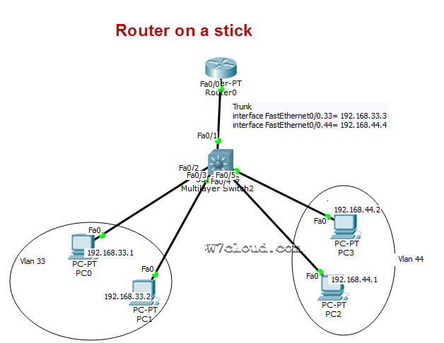
Design the lab according to following figure and we have four PC/host PC0 & PC1 are belongs to vlan 33 and PC2 & PC3 are belong to vlan 44. Configure the each device according to following configuration.
Switch configuration:
Four ports are required to be configured as access ports because these ports are connected with the PCs. We will assign the vlan 33 to port2 and port3 as it is in vlan 33, while other ports will be assign with vlan 44.
Switch(config)#interface range fastEthernet 0/2 – 3
Switch(config-if-range)#switchport mode access
Switch(config-if-range)#switchport access vlan 33
% Access VLAN does not exist. Creating vlan 33
Above Command will create the vlan 33 automatically on switch.
Switch(config-if-range)#exit
Switch(config)#interface range fastEthernet 0/4 – 5
Switch(config-if-range)#switchport mode access
Switch(config-if-range)#switchport access vlan 44
% Access VLAN does not exist. Creating vlan 44
Switch(config-if-range)#exit
Switch(config)#exit
There are five ports of switch which are involve in this lab, port fastEthernet 0/1 is connected to swich therefore we configure this port as trunk with encapsulation dot1q for inter-vlan routing. Host ports associated with the proper VLANs, we now need to allow this VLAN traffic to be brought up to the router to be “routed”. We will accomplish this by setting up a link called a trunk. A trunk will allow for multiple VLANs to traverse the connection to the other device so that it can be processed.
Switch(config)#interface fastEthernet 0/1
Switch(config-if)#switchport trunk encapsulation dot1q
Switch(config-if)#switchport mode trunk
Switch(config-if)#exit
We will also set the layer 2 trunking encapsulation type, there are 2 for these switches, ISL (Cisco) and
Dot1Q, Dot1Q being an open standard. We will use Dot1Q. Use the “switchport mode trunk” and “switchport trunk” commands to accomplish this task.
Router configuration:
We will need to configure our router to accept frames over our trunk for both VLANs 33 and 44. Identify the interface on the router you used for the trunk to the switch. The first command you should do is a no shutdown and then you need to use “’Sub-Interfaces” in order to use one physical interface to represent two virtual interfaces. we will create two sub interfaces in this lab i.e. interface fastEthernet 0/0.33 & interface fastEthernet 0/0.44
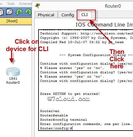
Router>enable
Router#conf t
Router(config)#interface f0/0
Router(config-if)#no shut
Router(config-if)#exit
Router(config)#interface fastEthernet 0/0.33
Router(config-subif)#ip address 192.168.33.3 255.255.255.0
Router(config-subif)#encapsulation dot1Q 33
Router(config-subif)#no shut
Router(config-subif)#exit
Router(config)#interface fastEthernet 0/0.44
Router(config-subif)#ip address 192.168.44.4 255.255.255.0
Router(config-subif)#no shu
Router(config-subif)#encapsulation dot1Q 44
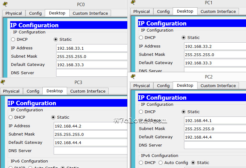
PC or Host configurations:
Assign the IPs as per diagram and set the default gateway IP address for hosts. For vlan 33 hosts have the gatway 192.168.33.3 because we have configured a sub interhace on router for this vlan with IP 192.168.33.3 and 192.168.33.4 will be gateway for vlan 44. See the following figure to verifying this configurations:
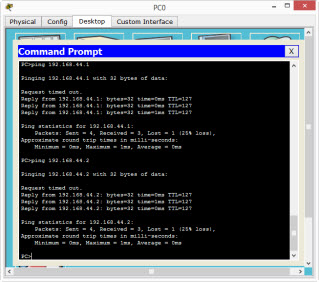
Lab connectivity verification:
Once you have done the above configurations you can now begin the process of verifying our configurations. Let’s check our hosts. First, ping their gateway to see if they can reach the router and then ping the PC3 from PC0 or PC1. In case of correct configuration this ping will be successful.
If you have trouble with this lab you can watch Router on stick configuration Video: